Quantcast
Channel: Motor drivers forum - Recent Threads
Viewing all 22144 articles
Browse latest View live

RE: DRV595: application related question

$
0
0
Hi Lilian,
Could ytou please let me know whether the 5A output current is transient value or continuous value? How much is the PVCC and load resistance?
Best regards,
Shawn Zheng

RE: DRV8801: VPROPI driven low problem

$
0
0
Hi Rick,

Great. Thank you for updating me - very useful !

Gene

RE: DRV10970: Direction Control

$
0
0

Hi Cole-san,

Thank you for your prompt reply.

I understood and will contact you if I get additional questions from our customer.

Best regards,
Kato

RE: DRV8432: Fault Pin behaviour in cycle by cycle mode

$
0
0

Hello James,

our customer would like to ask another question about that driver.

Is there any “OC Latch Mode” In the “1PFB” configuration (Mode Pins set as 0 1 0) which could be adjusted by “’OC_adj” resistor?

Best Regards.

Vitali  

DRV8432: Fault Pin behaviour in cycle by cycle mode

$
0
0

Part Number: DRV8432

Hello,

I've got a question about "FAULT_N" Pin from DRV8432. When the driver is in the cycle by cycle mode (18.7A, two DRV8432 in parallel mode), we see some fine "Low" peaks on the "FAULT_N" output while that pin remaning "High". Radj=24K. Is that behaviour from "FAULT_N correct?

Best Regards.

Vitali Lach

RE: DRV8703-Q1: Double-confirmation about /FAULT & /WDFLT State during Sleep mode

$
0
0
Hi Sakai-san,

The /FAULT and /WDFLT pins will be high z when the device is in sleep mode.

DRV8703-Q1: Double-confirmation about /FAULT & /WDFLT State during Sleep mode

$
0
0

Part Number: DRV8703-Q1

Dear, Sir. 

The design at my customer side using DRV8703-Q1 is proceeding well.

So they have started the reviewing of functiions which DRV8703-Q1 has.

The question is /FAULT & /WDFLT state during Sleep mode. 

I suppose it will be OPEN(Hi-Z) state because open-drain structure, but

I would like to double-confirm that. 

Sorry to ask about this kind of matter, but please give your advice. 

Best Regards, 

H. Sakai

RE: DRV8814: Control the decay mode with synchronizing AENBL

$
0
0
Hi Mukuno-san,

The customer can change the decay mode as proposed. There may be a delay of ~1us for the decay mode to change.

DRV8814: Control the decay mode with synchronizing AENBL

$
0
0

Part Number: DRV8814

HI DRV team,

My customer have a question.

They want to control the decay mode with synchronizing AENBL. (It have a few delay time. )

DECAY = L (Slow decay mode), At AENBL=L

DECAY = H (Fast decay mode), At AENBL=H

(Background)

At AENBL=H, they want to set low current limit(under 0.35A). If the decay mode is slow decay, motor current didn't decrease to current limit..

Also, They want to use brake mode at AENBL=L(stop motor).

RE: DRV8801A-Q1: Effects of exceeding abs. max. ratings and driving in continuous overcurrent, short-circuit

$
0
0
Hi Martin,

"How would the lifetime of the driver be affected if it experiences a continuous overcurrent at the H-bridge outputs? I.e. if the driver will keep retrying indefinitely?

In case of a short circuit (in the driver IC), is there a risk that the part will catch fire?
If yes, how will the driver behave (open-mode or short circuit)?"

The device is designed to protect itself by limiting the current in the event of a short circuit, and allow the heat inside the device to dissipate from the short circuit event before retrying. nFAULT is asserted to notify the system of a fault.

There should be no risk in normal operation.


"What is the consequence if the supply voltage pin experienced a transient voltage higher than 40V?"

Please see footnote (1) below the Absolute Maximum Ratings table of the datasheet:

(1) Stresses beyond those listed under Absolute Maximum Ratings may cause permanent damage to the device. These are stress ratings
only, which do not imply functional operation of the device at these or any other conditions beyond those indicated under Recommended
Operating Conditions. Exposure to absolute-maximum-rated conditions for extended periods may affect device reliability.

RE: DRV8843: Some questions

$
0
0
Hi Matsumoto-san,

Correct. The DRV8870 is more expensive per channel. But only one channel is required to operate the motor.

The DRV8870 VREF can be adjusted to raise or lower the current limit of the DRV8870.
Also signals need to be controlled at the inputs of the device.

We will continue to check into the your question on configuring the DRV8843.

RE: DRV8313 EFT/Burst Test

$
0
0
Hello,
I apologize but we do not have a solution to sit on 48V lines.
However I will say you are correct that putting TVS diodes could protect for EFT however it may be difficult to find a device that has the EFT rating at such high a voltage rating. Not because they maybe couldn't pass it but because it is not commonly specced for TVS manufacturers.
Regards,
Cameron

DRV8313 EFT/Burst Test

$
0
0

Part Number: DRV8313

Hello,

If we want to pass EFT/Burst tests do we need to put extra TVS diodes on the motor phases(Outputs of DRV8313)? 

What is the proper TVS diode then? I can't find proper TVS diode suitable for 48V motor and clamps 65V.


Do we need to pass this standard tests when motor and driver are close to each other with short cables ? which protections should be considered with this chip?

Thanks in advance.

RE: DRV8801A-Q1: Effects of exceeding abs. max. ratings and driving in continuous overcurrent, short-circuit

$
0
0
Hello Mr. Duncan,

I have a fellow-up questions about the driver,

(1) It is still unclear for me what will happen if the driver experienced a transient voltage higher than 40V? will the driver internal circuit get short-circuited (which means it would be a potential fire hazard)?

(2) If there was no Microcontroller that checks the nFAULT pin and there was short circuit at the motor, I know the driver will switch OFF the outputs if the current if more than I(PEAK) and wait for a time t(OCP) and then retry again. If this cycle continues indefinitely, what will happen to the driver's lifetime?

I hope you can help me with these questions.

Thanks
Mohamed Elamin

RE: DRV8313: DRV8313 Current sensing advice for a micorcontroller

$
0
0
Back EMF can be measured in multiple configurations, you may get a better idea here: www.ti.com/.../technical-documents.html. There should be numerous reference papers on the topic of spinning BLDC, ACIM and PMSM motors with both sensored and sensorless feedback, in a variety of different drive topologies.

Full disclosure, I work for the C2000 MCU department of TI and have little knowledge of the MCU that you've posted above. A quick glance shows that the device incorporates 12-bit SAR ADCs, which may be used to sense the phase current and DC bus voltage, which are typically the minimum you need to sense back EMF.

You may be interested to also evaluate our InstaSPIN solution, which can greatly reduce development time when designing motor drive systems

www.ti.com/.../LAUNCHXL-F28027F

When coupled with an integrated driver and reference software, you can start to spin your motor sensorlessly in minutes

www.ti.com/.../boostxl-drv8301
www.ti.com/.../motorware

Sean

DRV8313: DRV8313 Current sensing advice for a micorcontroller

$
0
0

Part Number: DRV8313

HI,

I have been successful driving a DRV8313 with multi wheel robotics using Gimbal motors like the small ones found on quad copters.  Currently I use an ESP32 and a table array to create the waveforms needed for the drv8313.  This works ok but I would like to try and improve the smoothness of the drive and increase speed and torque.

The esp32 datasheet

https://www.espressif.com/sites/default/files/documentation/esp32_datasheet_en.pdf

 I guess I am looking to measure some BACK EMF of the motor coils and use it to adjust the phase skew in an attempt to reduce some cogging.

Im looking for advice suggestions for components to have some sensor feedback to a Microcontroller.  

I could probably write the software if I had a general idea of how to also setup the hardware.  I have a number of free input GPOI0 pins to read voltages.

Any how i have looked through most of the internet for quite some time to get to this point but I am stuck

Any help greatly appreciated also if you ask questions I will try to be quick to respond.

Cheers

Adam

DRV8308: DRV8308

$
0
0

Part Number: DRV8308

Hello,

We are trying to use the drv8308 with closed loop operation. After a few days of testing we were able to get the drive to work with different voltage and motors to simulate manufacture variance. Now we need to be able to determine how 'loaded' is the system so we can report that our product is not within the predefined production tolerance.

It is possible to read the resultant gain when working with Clock Frequency Mode trough SPI? If not, what is the alternative? Or it is not possible?

Thanks

DRV8308: DRV8308: How to limit startup current?

$
0
0

Part Number: DRV8308

We are having trouble limiting the startup current with Clock Frequency Mode.

Our startup can peak as up as 24A depending on motor and input voltage configuration (24V+-10%)

According to the data sheet, the SPEED register should adjust the open loop gain before Lock, but in our tests it actuality apply a gain in CLKIN resulting in a lower speed after LOCKn, and do not affect to the start current.

Our Risense is 0,02 ohms

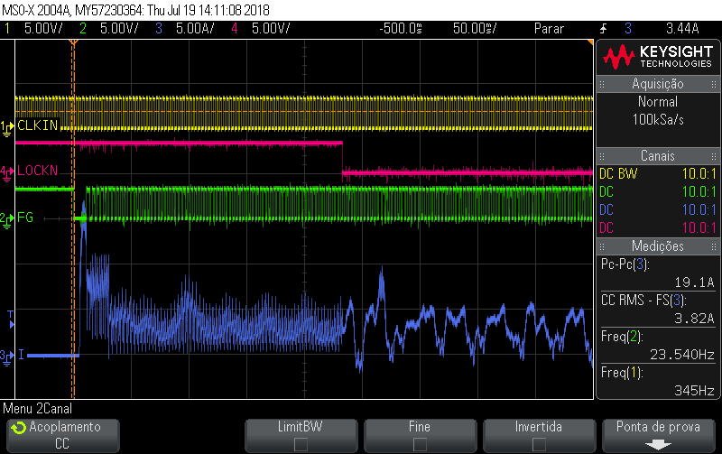
Here follow a 17A peak example, best result reached so far:

Our register configuration:

drive,speed_mode=<0>;        /* closed loop mode*/
drive,pwmf = <2>;            /* external FET Pwm frequency 100Khz*/
drive,fgsel= <1>;            /* xor all 3 hall sensor */
drive,aa_setpt = <5>;        /* ~95Hz */
drive,ag_setpt = <7>;        /* ~382Hz */
drive,advance = <43>;        /* ADVANCE */
drive,minspd = <5>;            /* Minimal speed for lock */
drive,spdrevs = <20>;        /* Hall Us required for lock */
drive,mod120 = <3970>;        /* fixed for closed loop mode */
drive,intclk = <5>;            /* Integrator clock */
drive,spdgain = <11>;            /* closed loop gain */
drive,filk1 = <1200>;        /* FILK1 */
drive,filk2 = <950>;        /* FILK2 */
drive,cmpk1 = <280>;        /* CMPK1 */
drive,cmpk2 = <560>;        /* CMPK2 */
drive,loop_gain = <240>;    /* closed loop gain */
drive,speed = <2000>;        /* open loop gain ???*/

SPI write debug to confirm the data:

reg00 = [71]  [84]
reg01 = [00]  [2b]
reg02 = [14]  [05]
reg03 = [6f]  [82]
reg04 = [01]  [43]
reg05 = [50]  [0b]
reg06 = [04]  [b0]
reg07 = [03]  [b6]
reg08 = [01]  [18]
reg09 = [52]  [30]
reg0a = [f0]  [f0]
reg0b = [07]  [d0]
reg2a = [00]  [00]

Any Idea to what

Current Driver for Nano positioning

$
0
0

I am designing a moving magnet actuator for nano positioning application and need a linear servo driver that could operate it in the current mode. My requirements are  - Current driver that could run a 400 mH and 21 ohms coil in the actuator at a current closed loop bandwidth of 1000 Hz and has a noise floor of 10 nV/sqrt(Hz) or 10 micro volts rms till 1 MHz or lower noise floor. I am also want the driver to give at least 2-3 A continuous current. Does TI have any current driver that meets these specifications.

DRV201: no VCM current output at mid-high current setup.

$
0
0

Part Number: DRV201

Hi,

I just run into some trouble using the DRV201 driver to drive a VCM for a research project. 

With the DRV201 evaluation board, it worked completely fine through the full range, However, once I switched to my own DRV201 adapter board, the driver fails at ~400 normalized VCM current. Beyond that current, when I update the current output, the driver will try to raise the current and rapidly drop to 0. No error is reported from the registry. 

I have tried quite a few different things to solve the problem (soldering technique, PCB spec and capacitor location), but the error kept happening. The board is extremely simple and almost identical to the evaluation board. I have not clue how to troubleshoot. At this point, any insight or suggestions will be helpful.

Some additional comments:
I just figured that above ~400 normalized current, the driver actually reset it self whenever I setup an output current. PWM/Freq settings are all reset to default. Without any VCM connected, the device reports a no connection error at any voltage output, which indicates no short connection.

Viewing all 22144 articles
Browse latest View live


<script src="https://jsc.adskeeper.com/r/s/rssing.com.1596347.js" async> </script>