Hi After the yellow circle, the current waveform becomes somewhat flat (see below), Under load how is the area effected, is this the normal for fixed decay?
↧
Motor Decay
↧
RE: DRV8872-Q1: Rds_on vs Iout worst characteristics
Hi Yoshida-san,
For number 2 and 3, the typical number is at 25C and 24V.
For number 2, the maximum is across temperature and voltage.
For number 3, the maximum is across temperature with Iout=1A.
Please note the statement at the top of the Electrical Characteristics:
Over recommended operating conditions unless otherwise noted. Typical limits apply for TA = 25°C and VVM = 24 V
We do not have data for number 1. What current and voltage does the customer intend to use?
↧
↧
DRV8872-Q1: Rds_on vs Iout worst characteristics
Part Number: DRV8872-Q1
Hi support team,
In order to identify the worst conditions under their use conditions, out customer would like the following data.
1. Rds_on vs Iout Graph worst condition
2. RDS(on) vs Tj worst condition
3. VTRIP vs Tj worst condition
For the number 2 and 3 above, there was a typical conditionand ambient temperature in the data sheet.
Although the design must be established under the worst condition in their use conditions, the worst condition of the electrical characteristics of the data sheet is more stringent than their condition.
Is there no way to calculate the worst value under usage conditions with simulation etc. even if there is no graph?
Best regards,
Tomoaki Yoshida
↧
RE: DRV10975: DRV10975 EMC ISSUES
Hi,
Sorry to hear that it did not improve the performance. I would like to suggest 2 more experiments.
1. Can you force Vreg pin to 1V higher than regulation voltage? This will help us to identify source of the noise. For example, if you measure Vreg to 3.3V force to 4.3V and see performance is better. If vreg is 5V, you can force it to be 6V. Please make sure you force to the voltage when VCC is already up. Forcing the voltage will prevent switching activity for the Vreg.
2. place some capacitor value on the phase to ground and see it improves the performance. I will start with 1nF from all phast to ground. If this solve the issue, we have to make sure current through capacitor during swithcing does not exeed maximum peak current limit (2A). Cap will slow down PWM edges.
thanks,
Seil
↧
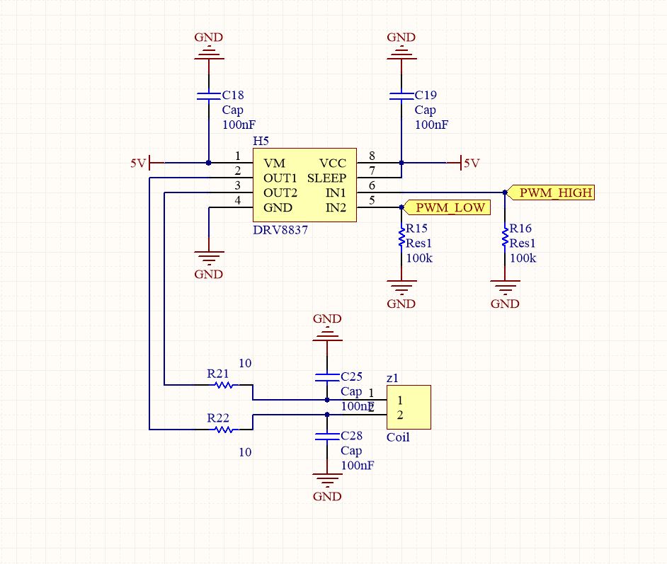
DRV8837: PWM problem
Part Number:DRV8837
Hi
I try to use the coil with a PWM of motor drivers. But there are some problems.
I use stm32f1 MCU, IN1 : 80% 400hz, IN2 : 0% 400hz PWM
output of the coil is abnormal...When you see the picture, the signal of OUT 2 is not zero..
Normally, OUT1 is 80% PWM and OUT2 is near 0???
Why are IN 2 and OUT2 different??


↧
↧
DRV8824: V3P3OUT capacitance
Part Number: DRV8824
Hello,
Our customer use the DRV8824, have a question about V3P3OUT capacitance.
TI recommend to connect the capacitance as 0.47uF between V3P3OUT and GND.
The customer want to connect a capacitance as 0.1uF or less.
Is there any impact to characteristics of 3.3V regulator?
Best Regards,
Naoki Aoyama
↧
RE: DRV8837EVM: DRV8837 PWM problem
Hi Lee,
Sorry for the delayed response about the bulk capacitor. Yes, .1uF (100nF) is probably too small. Please increase the cap.
Please start with 10uF in parallel with the .1uF.
Sorry for the delayed response about the bulk capacitor. Yes, .1uF (100nF) is probably too small. Please increase the cap.
Please start with 10uF in parallel with the .1uF.
↧
RE: DRV8837EVM: DRV8837 PWM problem
Hi Rick,
Thank for your response.
Yes, I replaced it larger than before. It's a little bit less noisy, but there is no significant change in the output signal.
And I tried to replace the Rod(coil) with a DC motor. In addition the diode(H-bridge) was attached to prevent a backEMF. but it is the same symptom.
Thank for your response.
Yes, I replaced it larger than before. It's a little bit less noisy, but there is no significant change in the output signal.
And I tried to replace the Rod(coil) with a DC motor. In addition the diode(H-bridge) was attached to prevent a backEMF. but it is the same symptom.
↧
DRV8837EVM: DRV8837 PWM problem
Part Number: DRV8837EVM
IN1 : PWM duty 80%, IN2 : PWM duty 0% / 400hz

Why is the IN2 and OUT2 different??
I think the back EMF is a problem... right?
↧
↧
RE: DRV10975: DRV10975 EMC ISSUES
Dear Seil:
Actually i do a test compared with TI drv10975 EVM . the conductive and disturbance power wave as fellow:


DEMO CONDUCTIVE WAVE DEMO disturbance power wave
I found only one point exceed the demand (at 400hz in conductive wave). so i prefer to optimized the pcb layout to match the demand.
i don't know why this point can exceed the test standards and how to solve the problems. thanks a lot .
↧
DRV10975: DRV10975 EMC ISSUES
Part Number: DRV10975
Dear TI:
I use drv10975 as BLDC Drive. The Moter output power is 4W, voltage:12v.
but when i do GB4343.1 Certification test, Conducted Disturbance and Disturbance Power are all excessive.


i try add a magnetic ring to the lead line and a magnetic bead on the power input, but it doesn't work.
so i add 471 cap between three-phase and GND , But it seems doesn't work either.
Can you give me some advise on the point ,thanks a lot.
by the way: parameter as follow.

↧
RE: DRV595 application circuit
Hi Simon,
Current resistor is used to snese the temperature on the module, and the onstant current source is used for reference. An error amplifier is used to combine, and the output of the error amplifier is then fed into the DRV595. You don't need to know the current through the bridge, because it's used to control the temperature on the module. Please refer to this document about how DRV device works. www.ti.com/.../sloa092.pdfwww.ti.com/.../spra873.pdf
Best regards,
Shawn Zheng
↧
RE: BOOSTXL-DRV8305EVM: When should I be running Lab 5b) ?
Hello,
I am writing to let you know that a C2000 team member has been assigned to this post and should be answering shortly.
Regards
Baskaran
I am writing to let you know that a C2000 team member has been assigned to this post and should be answering shortly.
Regards
Baskaran
↧
↧
BOOSTXL-DRV8305EVM: When should I be running Lab 5b) ?
Part Number: BOOSTXL-DRV8305EVM
Hi,
I am just getting started with lab5b) after ID ing my motor and after experimenting with Kp values and understanding a limit to my Kp based on the high freq noise, in lab 5a).
As a motor control beginner, I would like to know if there is a point evaluating gains with no load. These are bound to change when I connect my loads I am assuming.Is that right?
For my application, I will be taking feedback from a quadrature encoder for the position. Would I need to do lab 5b) even then?
As a follow up question, would the program qep.c and qep.h calculate the speed from the position? Or is that included in the actual code of lab 12a)
Thanks,
Sowmya
↧
RE: Motor Decay
Hi, Rick
Where the current flatten, is there a higher chance of missing a step?
Page 6 fig 7 of SLVA321–March 2009, shows a step of current. The current has a sawtooth shape. Why is this case?
When I applied a load to the stepper motor, the current draw from the power supply increase.
thank
Where the current flatten, is there a higher chance of missing a step?
Page 6 fig 7 of SLVA321–March 2009, shows a step of current. The current has a sawtooth shape. Why is this case?
When I applied a load to the stepper motor, the current draw from the power supply increase.
thank
↧
DRV8886AT: Auto Tune Ripple Control
Part Number: DRV8886AT
Hello,
Our customer use the DRV8886AT, have some questions about Auto Tune Ripple Control.
Could you tell me the level of IVALLEY?
I think that IVALLEY is xx% less than ITRIP. The customer want to know "xx%".
The customer have another question about application curves Fig.30 on the datasheet.
There are a lot of ripple noise. Does it really using Auto Tune Ripple Control?
Best Regards,
Naoki Aoyama
↧
RE: LMD18200: Bypass capacitance
Thank you for the answer.
We will take it into consideration.
Kind regards
↧
↧
DRV8711: need help to plot winding current
Part Number: DRV8711
Hi ,
1) Where should I connect my Oscilloscope probe to get the wave foam for winding current ?
2) I am not getting a smooth and fine wave foam when connect to the sensing resistor pads , why?
3) Is the current probe is must for doing the motor tuning?
I am using the Oscilloscope -RIGOL 1052E and the china stepper motor( I=1A ,R=6.6ohm, L=8.2mH) DPM57SH51-1A.
Please help.
↧
RE: DRV8886AT: Auto Tune Ripple Control
Hi Aoyama-san,
We will investigate and reply soon.
We will investigate and reply soon.
↧
RE: Motor Decay
Hi James,
Where the current flatten, is there a higher chance of missing a step?
>> There is a chance. Even if you do not miss a step, there can be vibrations plus inefficiencies due to higher RMS current.
Page 6 fig 7 of SLVA321–March 2009, shows a step of current. The current has a sawtooth shape. Why is this case?
>> I am assuming you are referring to the zoomed in section. Is that correct? This is the current regulation engine attempting to keep the current a specified level. To do so, current is injected into the winding until the desired level is reached. The decay section comes next. Slow decay (in the left circle) has less ripple but may not maintain proper regulation as we discussed earlier. Mixed decay (in the right circle) is not correctly described. The ripple should be larger than slow and remain the same throughout the image.
When I applied a load to the stepper motor, the current draw from the power supply increase.
>> How much difference did you notice at the power supply? Did you slow the motor speed to account for the load?
↧